This was a five weeks final project for the UCSC Mechatronics CMPE218 class. The purpose of this project was to provide an opportunity to apply all that we learned in CMPE‐118 to solve an open‐ended problem. The task was to build an autonomous robot capable to navigate the game field, locate and destroy the enemy ATM6’s (using ping pong ball ammo), and then shoot down Ren’s ship with a very well‐aimed shot.
The Background Briefing for the set up:
"The Rebel Alliance dealt a massive blow to the reconstituted Empire, the First Order, defeating their dreaded Starkiller Base, and giving rise to the voices of freedom throughout the galaxy. The First Order, however, has not been idle after this setback, and has massed forces ready to wipe out the Rebel Resistance.
First Order, led by the evil Kylo Ren, is preparing an assault on the Resistance Base on the planet Crait. A Resistance spy, Rey, aided by a sympathetic ex‐storm trooper, Finn, is leading the defense of Crait against a battalion of AT‐M6 armored walkers and Ren’s TAI Silencer ship.
The battle is critical to the survival of the Rebel forces. The Rebel Alliance has commissioned the CMPE‐118 class to game out possible solutions to the impending attack. Will you be able to help the Alliance survive the onslaught?"
The Team

Introduction
The purpose of this project is to design and implement a machine capable of solving a particular task. There are two major considerations in building this device. The device must finish the task without any human interaction. This means the robot must use sensors and time to figure out its course of action. The other factor is that the task to be solved changes slightly on every iteration. This means that the device must be flexible enough to account for this.
Problem Description
We are tasked with placing a standard size ping pong ball through targets of different types in field that is pseudo-randomly generated. We have two types of targets the ATM6 and the Ren.
The Field
The field is a white, IR reflective, 4’ by 8’ surface. The boundaries are delimited by a 2 inch wide black tape that is not IR reflective. There is a T shaped figure with tape that points to the Ren and there is also small pieces of tape in the middle of the field.
The ATM6’s
The ATM6 is 8” wide and 12” tall. Our goal for this target is to get the ping pong inside a 4” diameter hole centered 8” above the field. There will be 3 ATM6’s placed randomly on the perimeter of the field. For ease of finding, they are marked with a trackwire that emits a magnetic field that oscillates at a frequency of 25kHz. Once the ATM6’s are down the robot can proceed to attack Ren.
The Ren
The Ren is 12" wide and 16" tall . To complete the task the robot needs to place a ball inside the 2" hole 14" from the field. The Ren is always placed in the same position on the field, at the opposite side of the starting position of the robot.
Design Constraints
As described before the robot completing the challenge must be completely autonomous. This means it will get no human help while performing the task. The task must be completed under two minutes. We have 5 weeks to design, implement and test our ideas in groups of 3. The budget for this project must be kept under \$150 to avoid arms races of who can afford the nicest components. Since there is a public demonstration of this robots they must also be designed to be reasonably safe. (no compressed air mechanisms). Last but not least we had to constrain the volume of our design when the round starts to a cube of side 11".
System Architecture
The following diagram is system level depiction of our system. We had to design it with the constraints of the battery a LiFe 9.9 V battery and the constraints of the micro-controller a UNO32. The value of this schematics to us, is ensure that the voltage values are compatible and that we have enough digital and analog pins on the micro-controller for our design.
Mechanical Design
The mechanical design of this project was developed on SolidWorks. The design is intended to be built using a laser cutter as a main tool for prototyping. We used the equations feature of Solidworks to make it possible to easily change the material used in the laser cutter with the main variable being the material thickness. To maintain our final robot within the budget we used MDF for the entire prototype but these can be changed to foam core, acrylic or other material by changing the material variable of the SolidWorks design.
Module Layer Design
The main idea for the mechanical design of our robot is based on a multiple layer structure that allow us to separate the main subsystems of our robot and work independently on each of them to perform the necessary adjustments during the development of the prototype.
The following images show the conceptual drawings of our design, these initial concepts changed during the design and the construction process as will be further detailed in the following sections of this report.
Bottom Layer
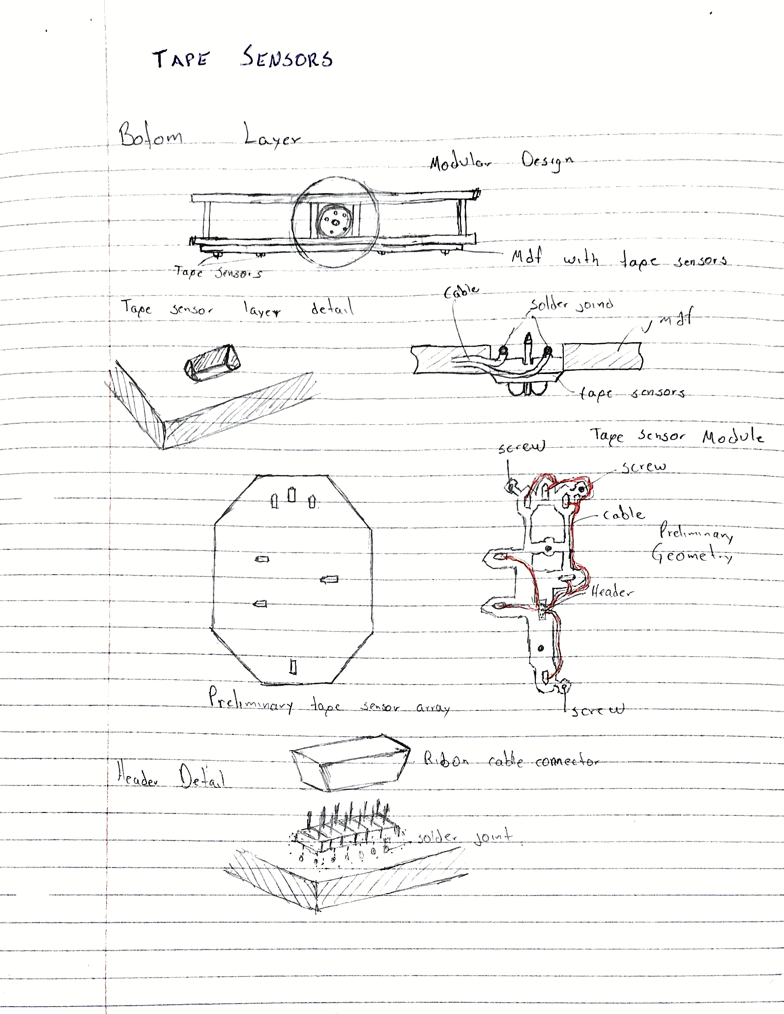
This layer consists of two main parts: The tape sensors layer and the motor layer. The Tape sensors layer is made out of Foam Core and was made by hand, so we did not used the laser cutter to build this layer in order to be able to modify it as fast as possible. The main concern during the design of this layer was the structural resistance of it as this layer has to be strong enough to support the other layers.
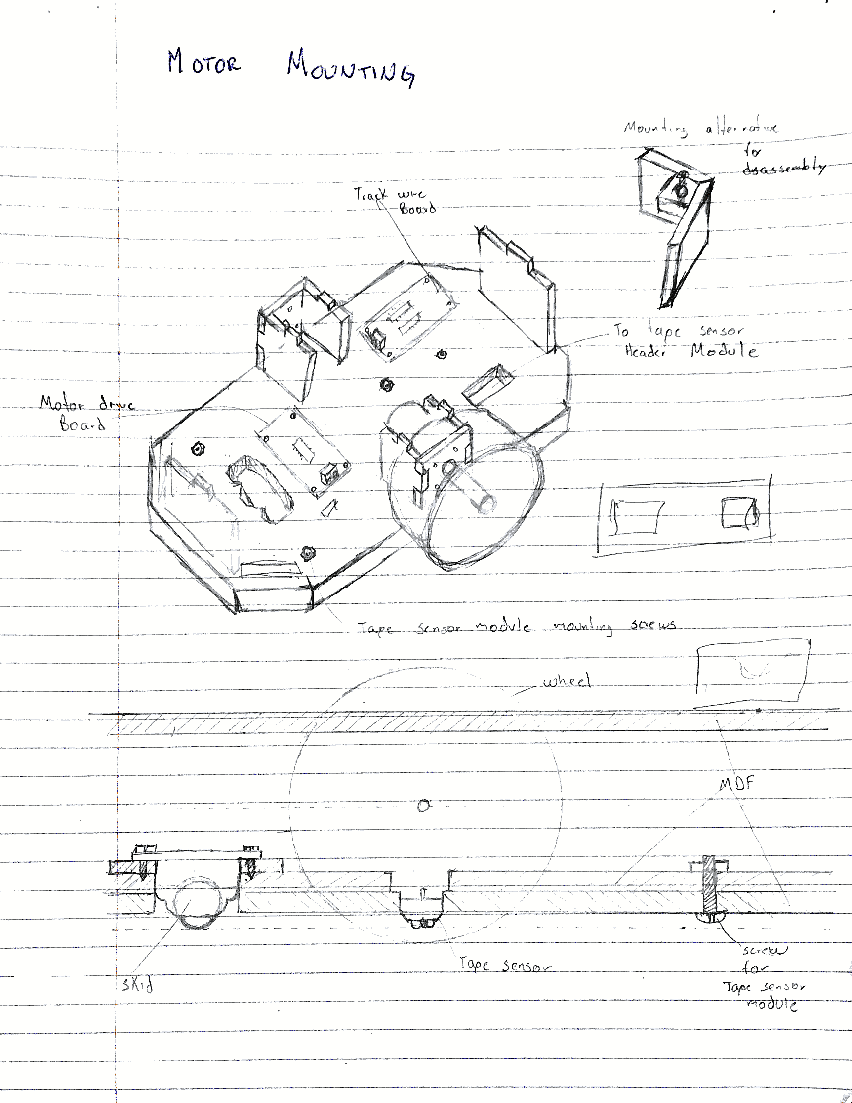
The following image show the CAD design of the Motor Layer, The actual prototype had minor modifications due to wiring and PCB board placement. Also is important to remark that the design consider accessibility to the wiring. The perforations in the walls of the chassis allow to inspect visually the connections but are also small enough to keep everything protected from the unavoidable bumps during operation.
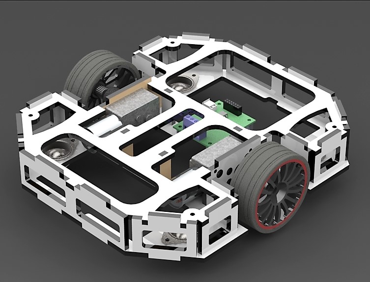
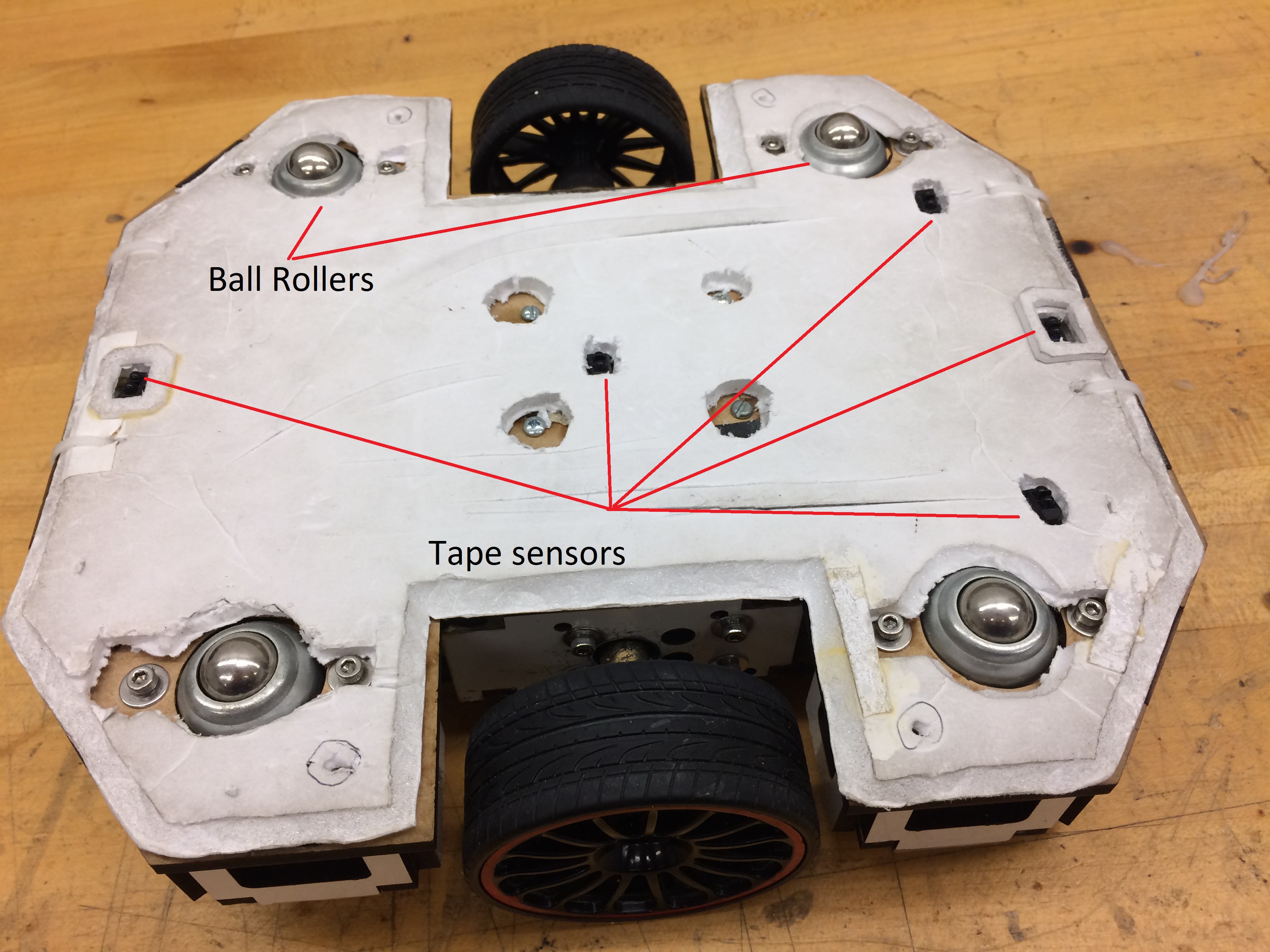
The final design is displayed in the following images. The main components of this layer are marked in red. One of the biggest challenges during the development of this layer was the ball rollers as it was very hard to mount them with the optimal height. When the rollers were too low the wheels had not enough friction and slipped on the field. On the other hand when the ball rollers were to high, the robot rocked back and forward to much. The numerous adjustments that we had to perform to the rollers proved the useful of the modular design as we only had to disassemble the bottom layer and work on it separately, leaving the other layers intact.
Middle Layer
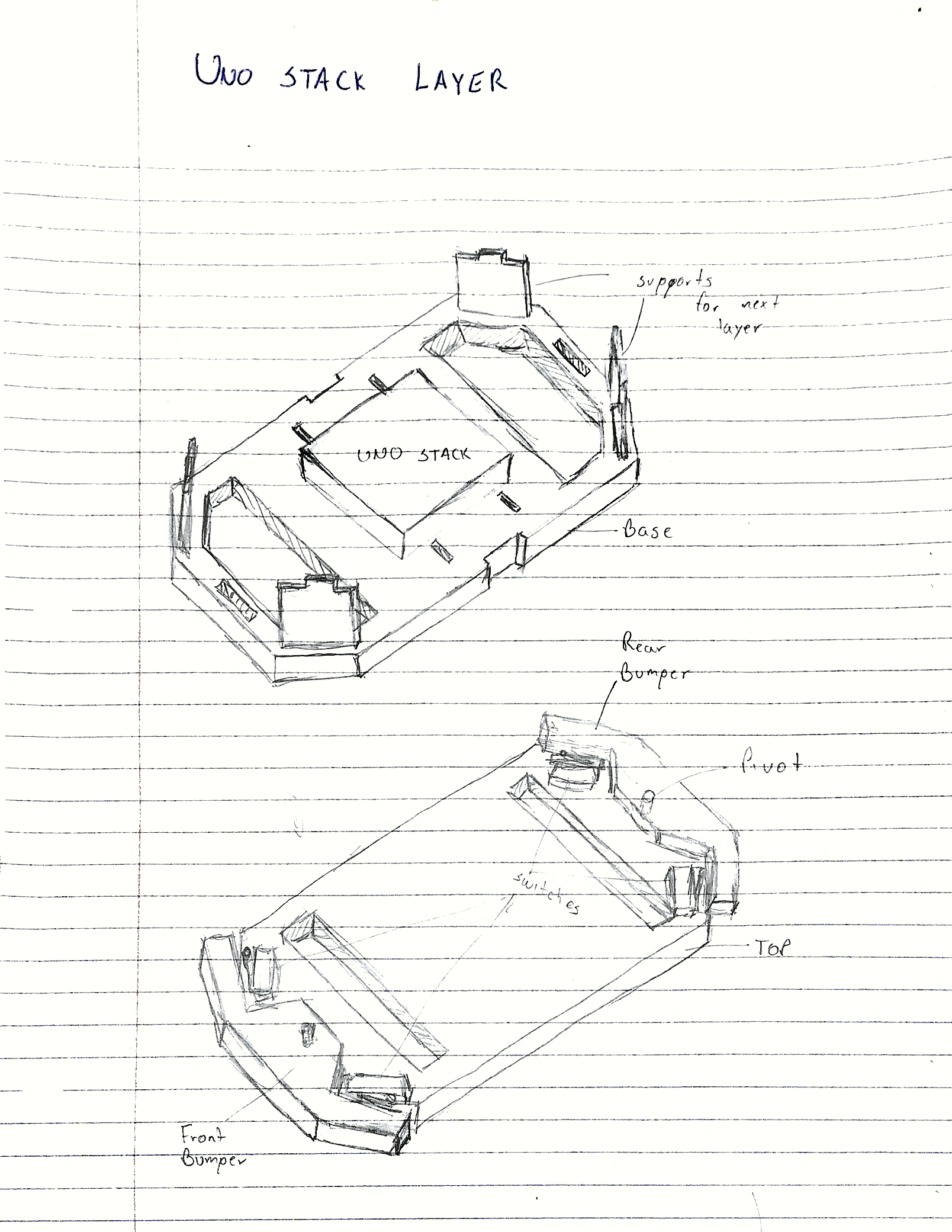
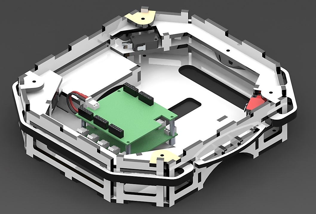
The middle layer or UNO Layer is the part of the robot that carries the most part of the electronics, is in a way the core of the robot. The design also integrates the bumpers mechanism and the track wire sensors. We followed the same approach and designed this layer in a way that allowed us to separate it from the other modules of the bot. The SolidWorks Design is displayed in the following image.
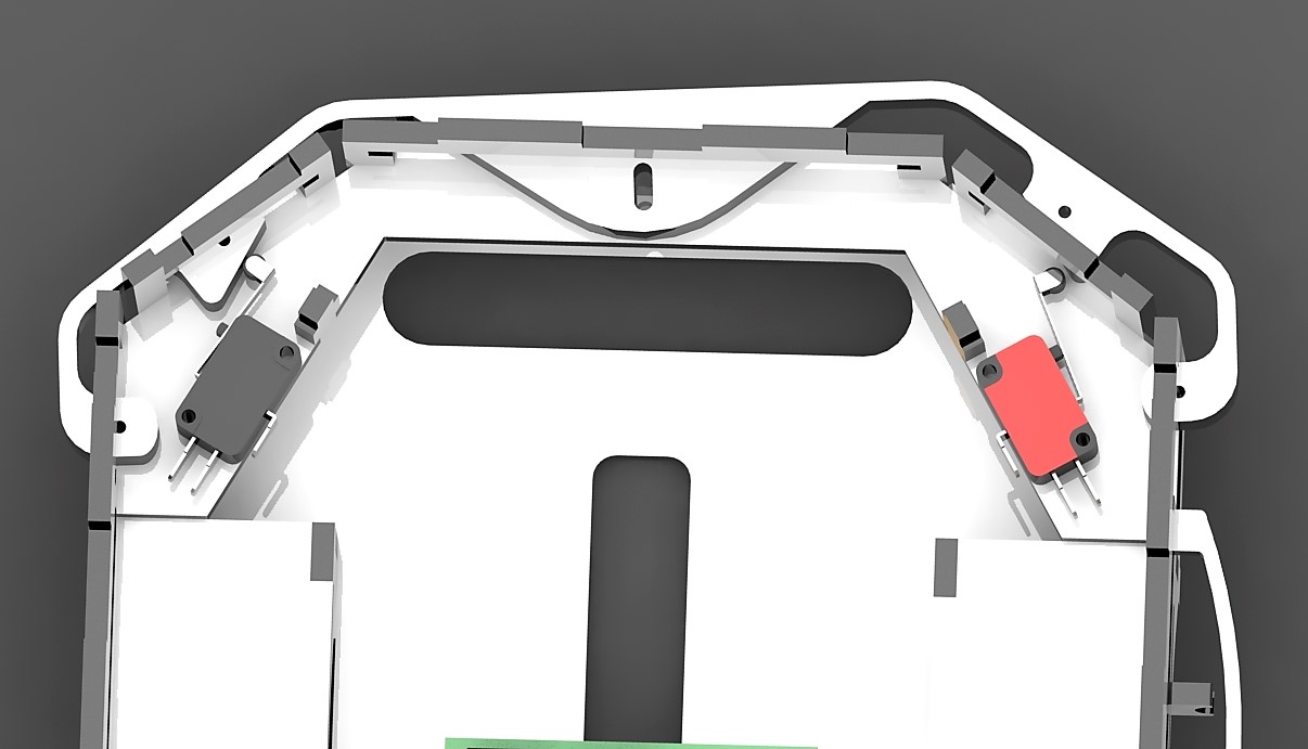
One of the most remarkable parts of the design of the middle layer are the bumpers. They are designed by modelling first the switch that we were using. Then, using the switch model to consider the angles and distances for the on and off positions we designed the actual bumpers. An image detailing the bumper when the robot bumps on the left side is shown below.
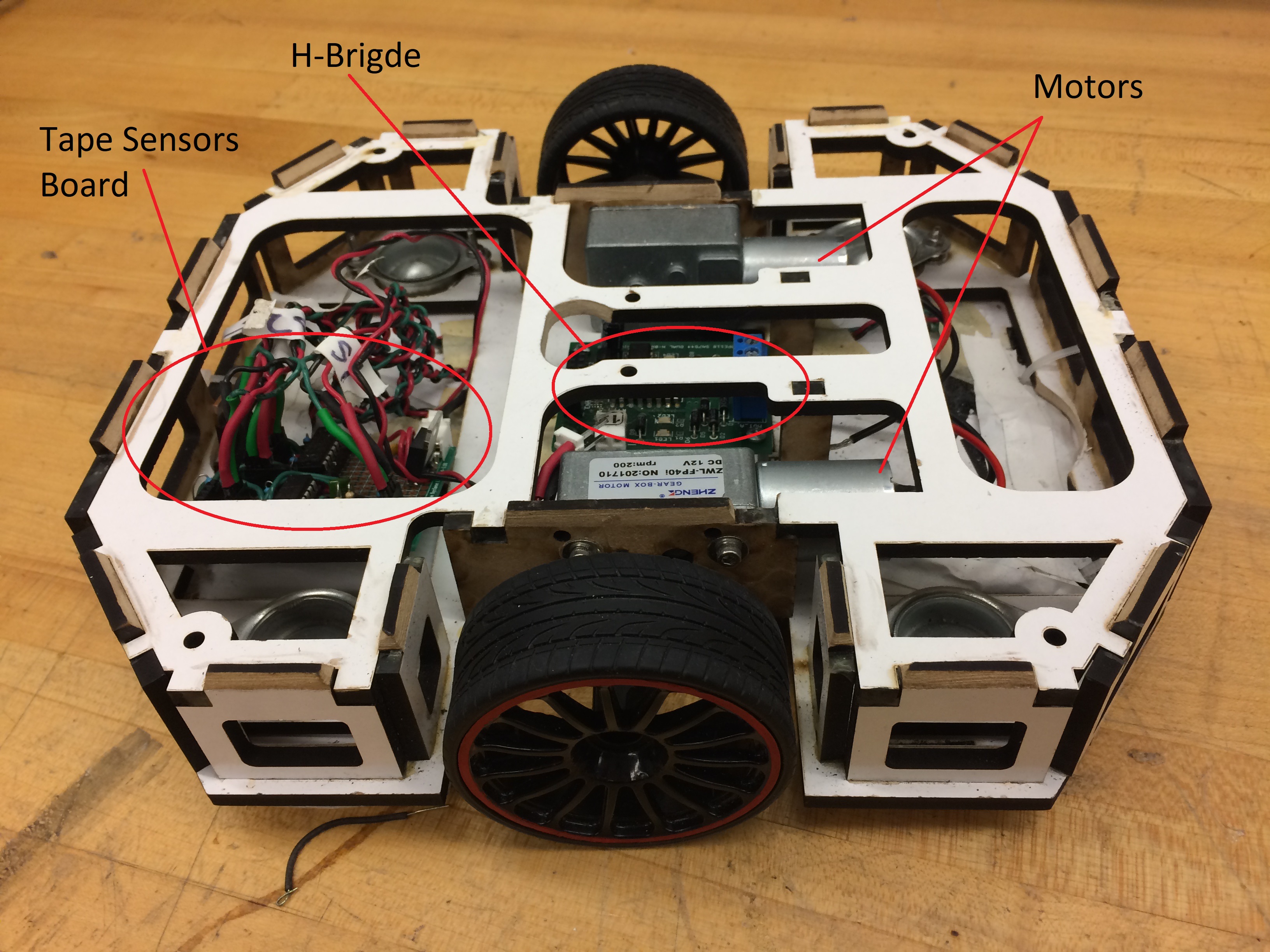
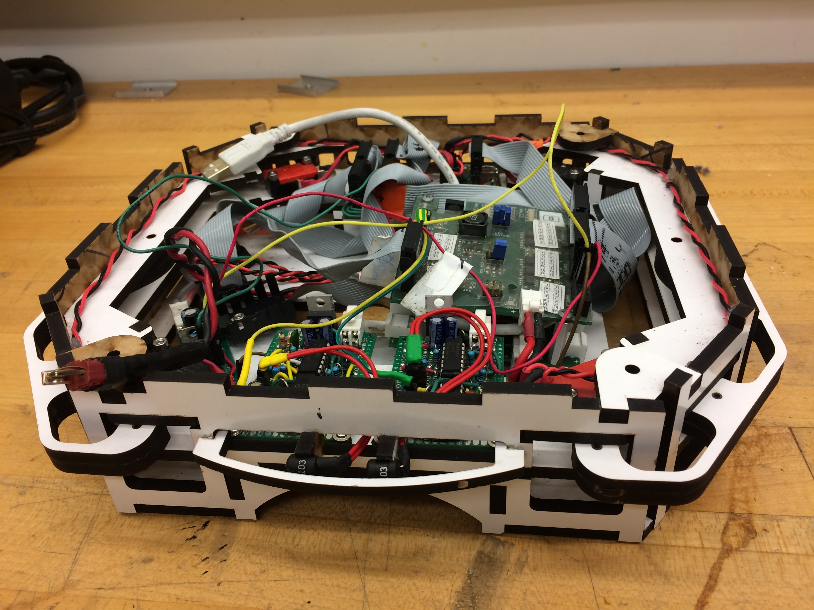
The final results of the construction are displayed in the following images. For this layer we faced almost any issue during the actual building of the prototype. However during the operation of the robot the curved edges of the bumpers generated some stuck issues with the obstacles that we did not anticipate beforehand.
Top Layer
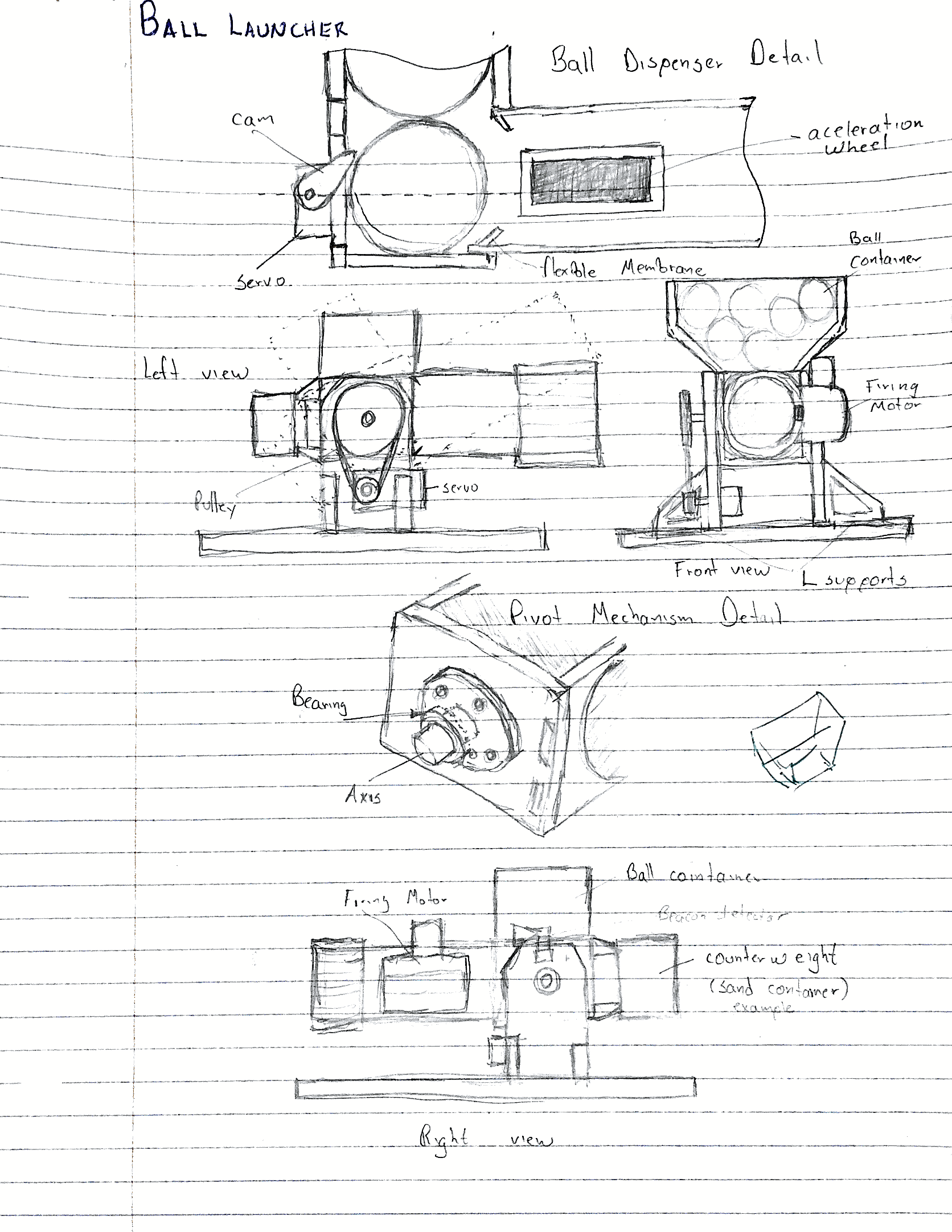
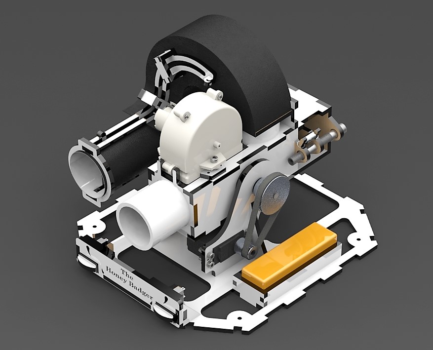
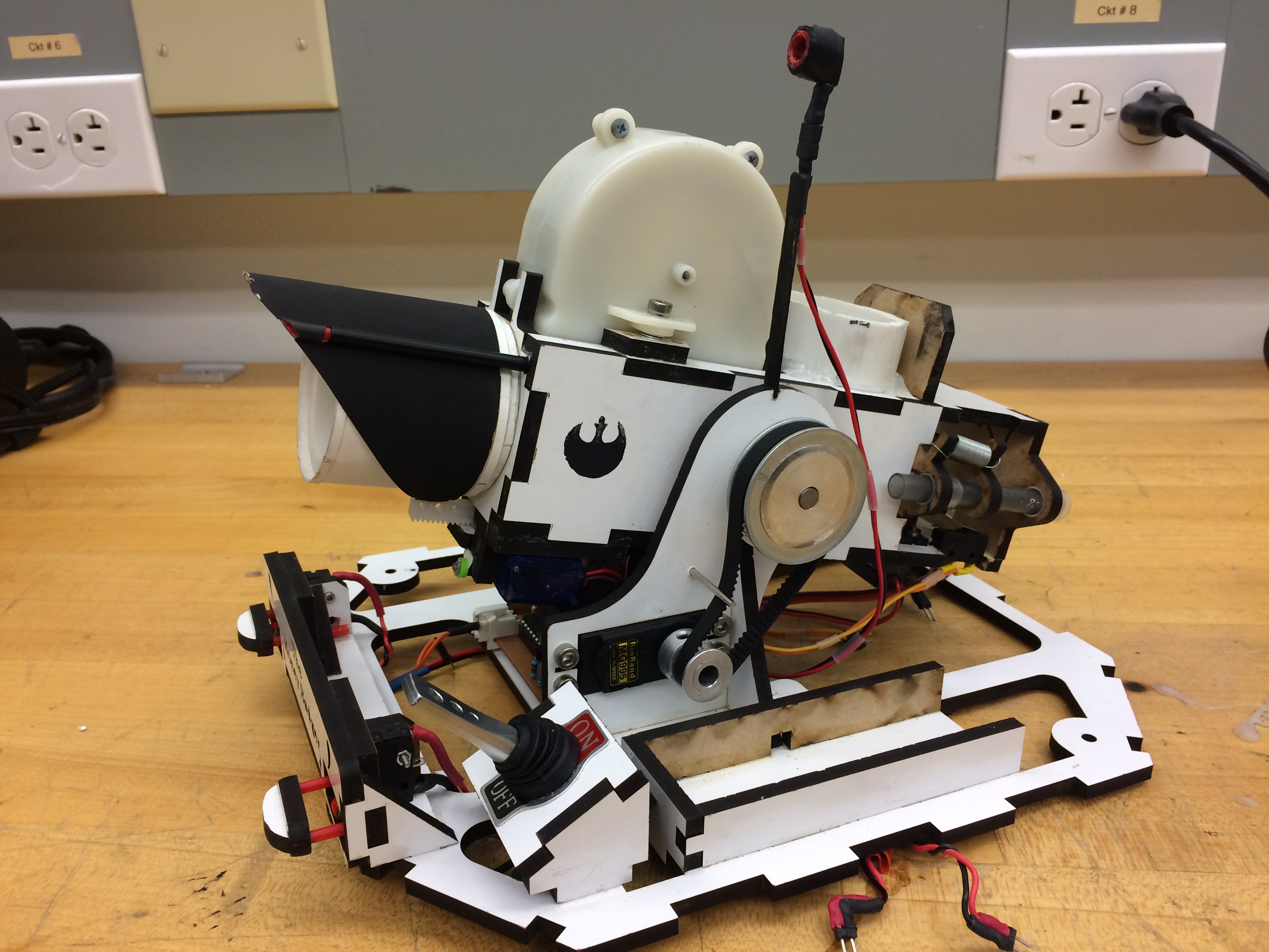
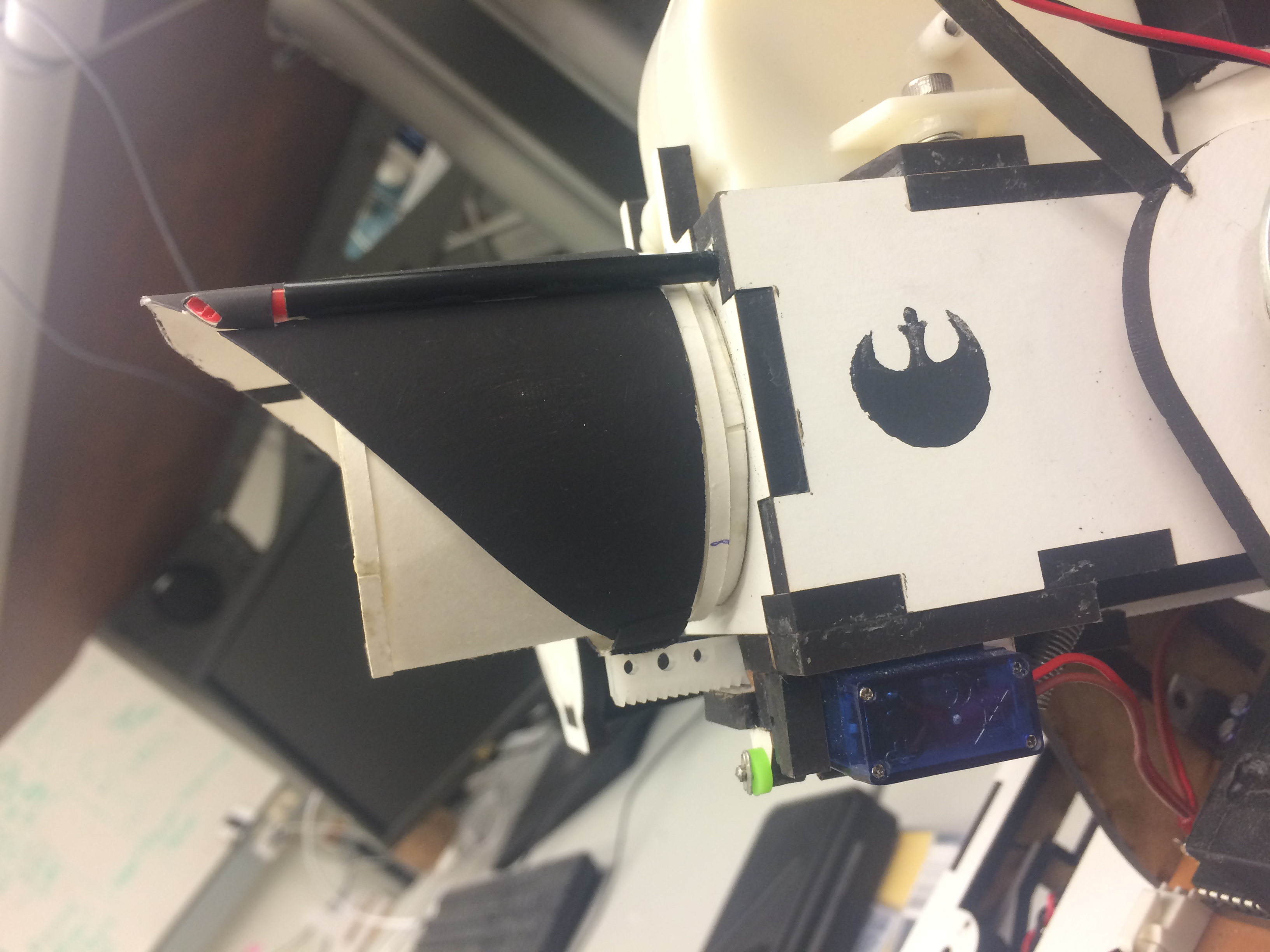
The top layer includes one of the most important mechanism, the shooter. Our approach to this consisted in an acceleration wheel for the actual shooting of the ping pong ball, a tilting mechanism to aim to the different targets, a cannon extension to improve our precision for the second target and the ball container with a rubber band mechanism to maintain the ball supply to the shooter. The following image shows the cad model of the top layer.
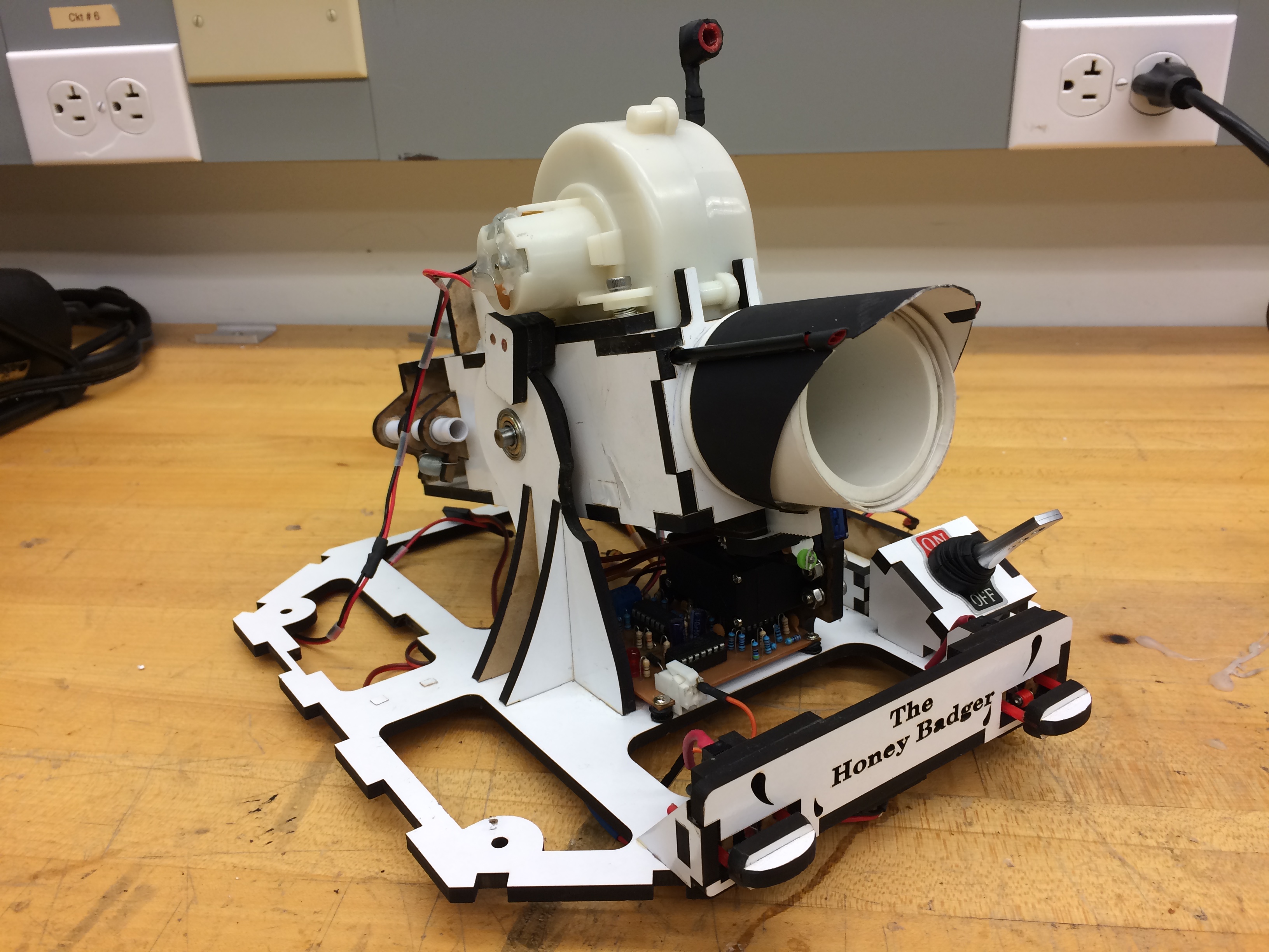
This was definitely the most difficult part of the prototype building, the trigger mechanism required a long stage of testing, adjustments and in certain point partial redesign. This will be further explained in the next sections. The final result is shown in the following pictures.
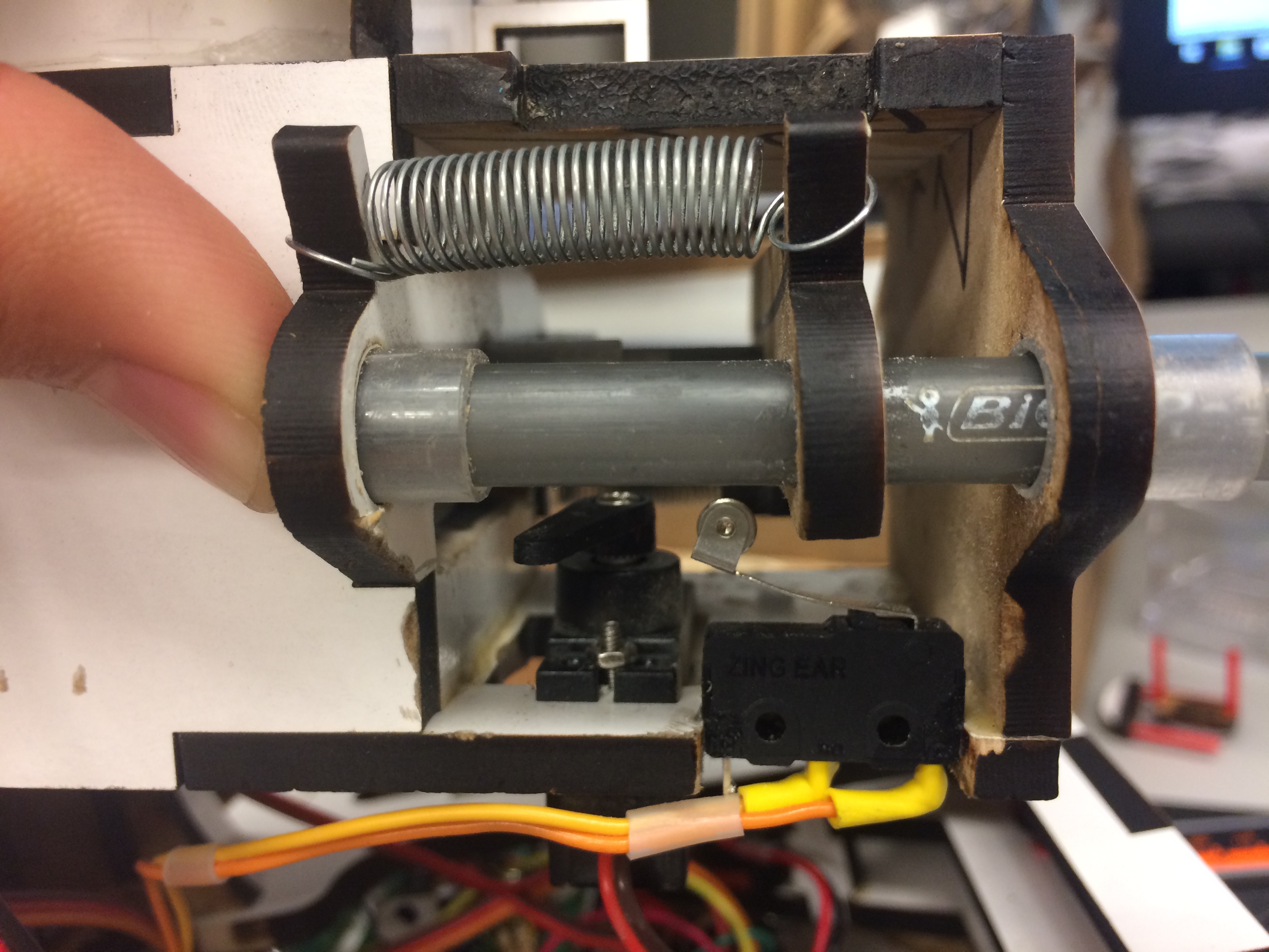
The trigger mechanism consist in a cylindrical metal bar that is activated by a servo motor and springs. This cylinder push the balls towards the acceleration wheel. The following images show the detail of the mechanism.
The loading mechanism is operated by a modified servo motor for continuous turning. This motor by the means of a cam mechanism pushes the cylinder base and the energy accumulated by the springs provide the impulse to the ping pong ball to reach the acceleration wheel. The limit switch is to stop the motor just when the maximum extension of the springs is reached and the mechanism have been released.
As mentioned before this part was the more challenging to make it work, the initial design is shown in the following image.
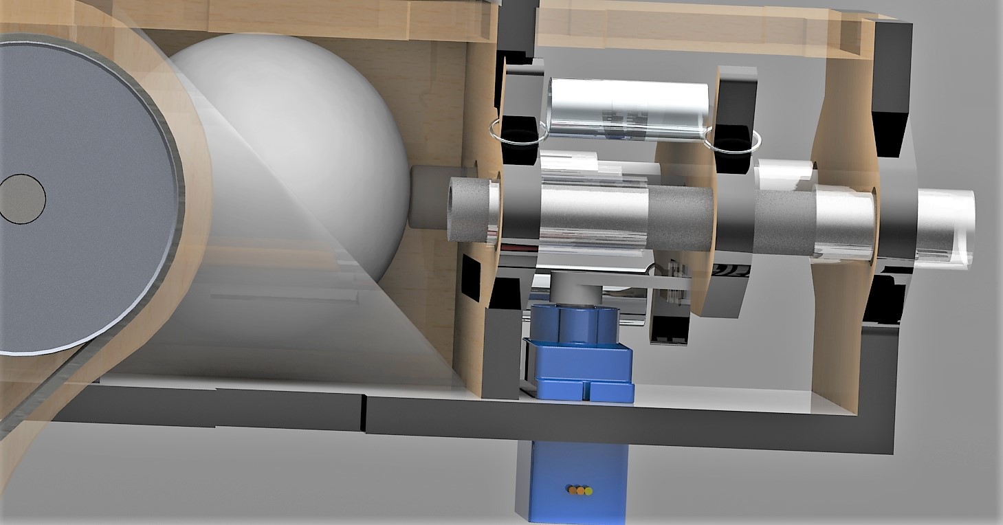
In this first design the placement of the servomotor was different. During our tests we find out that when the motor was in this position the energy of the springs was not completely release because the motor was not fast enough and in some point the cam interfered with the cylinder support regression. This problem was solved by changing the motor position in a way that allowed the complete regression of the cylinder base without interference.
Tilting
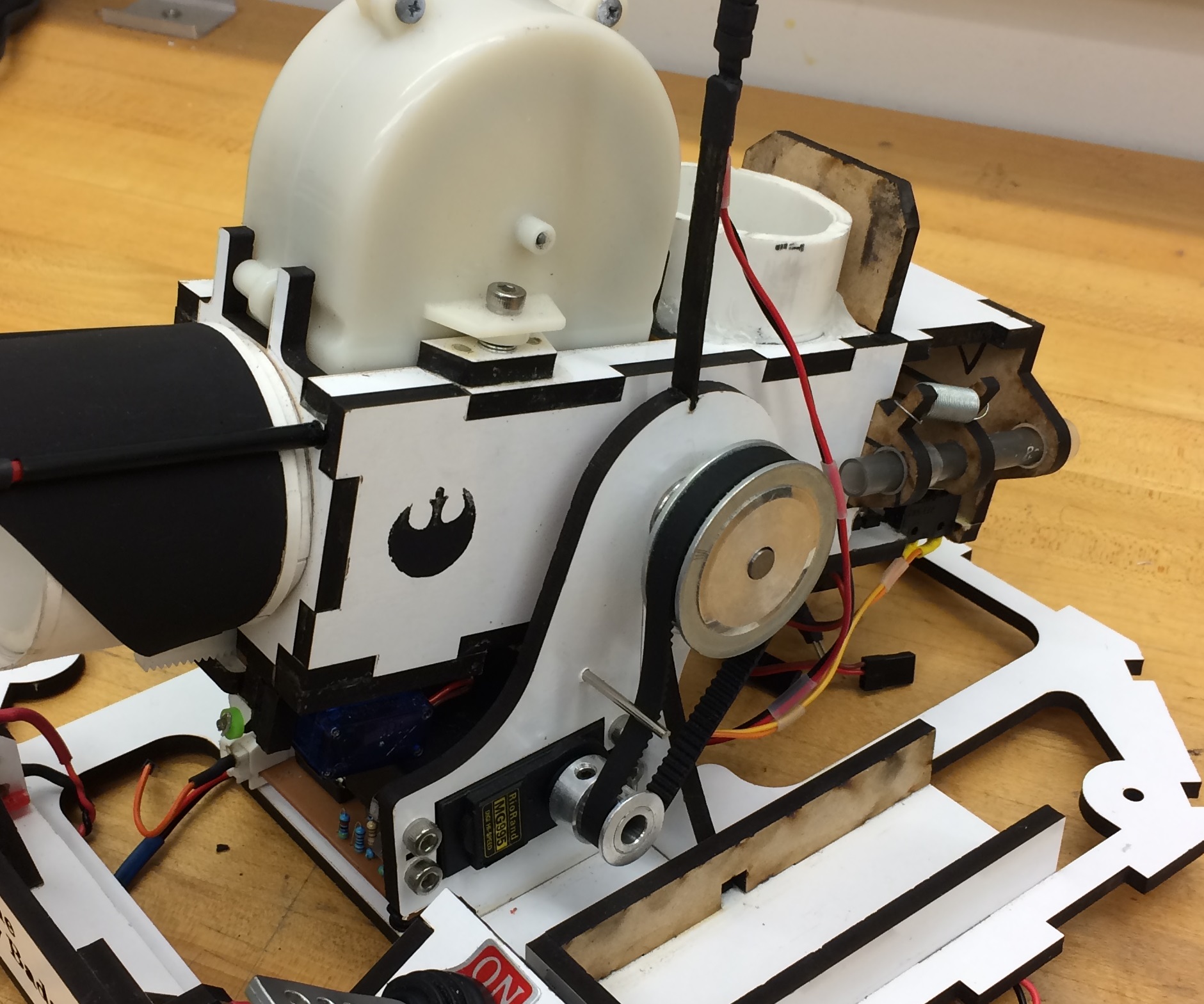
For the tilting mechanism we used a timing pulley attached to a servo motor to control the angle of the cannon. The design and final result is shown in the pictures below.
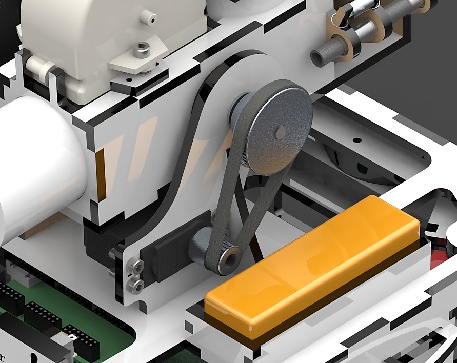
The main issue with this design was the adjustment of the belt, that is why we had to add an extra axis to increase the tension of the belt and avoid slipping.
Extender
The extension mechanism was designed and built to improve the precision of our robot. As the Ren target is so small during testing we found that a consistent shooting to the Ren target only with the shooter was extremely hard to accomplish, that is why we had to thing in a way to improve our chances to finish the task at the highest rate possible.
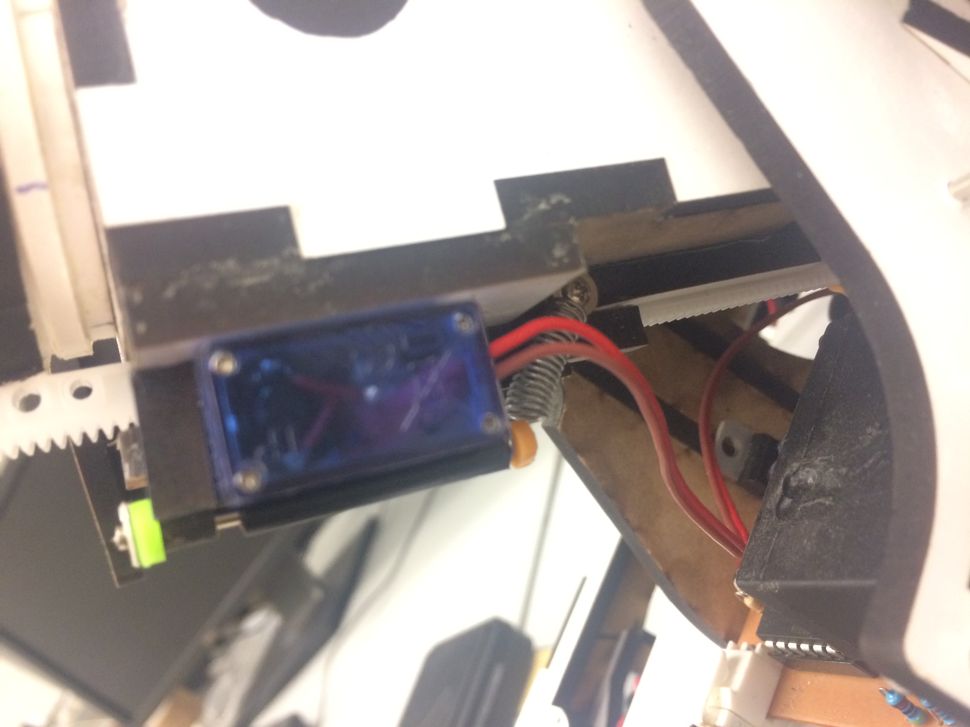
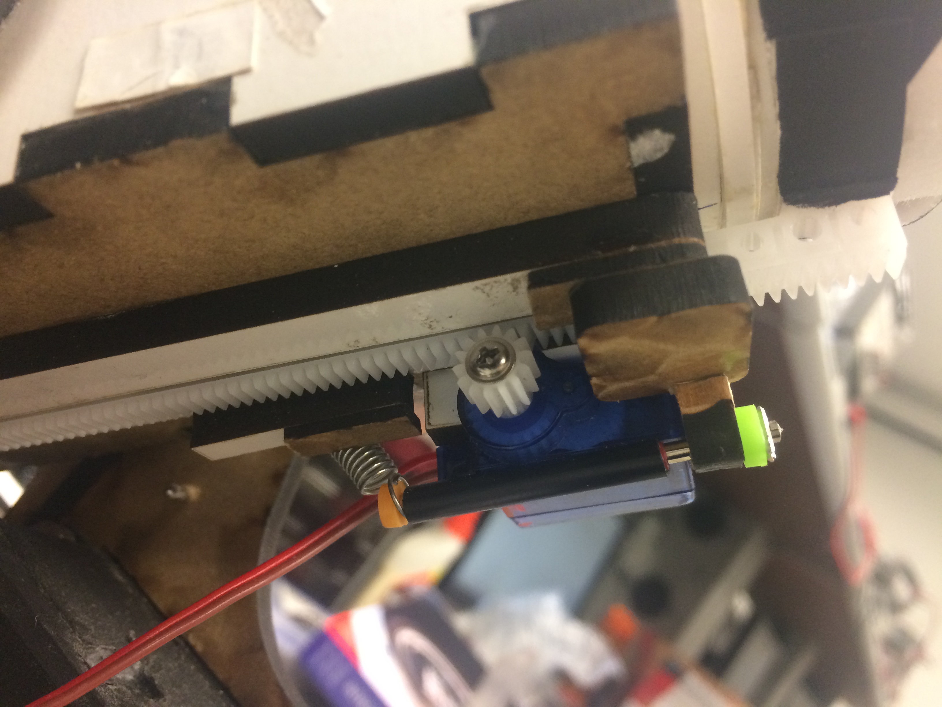
To save space and time we decided that the best way to implement this idea was to just drive the motor in one direction, so the extension of the cannon will be drive by our state machine, but the retraction will be performed manually. That is why we implement a spring mechanism that hold the motor an the gear in its position , but had the flexibility to “unplug” the rack and pinion mechanism.
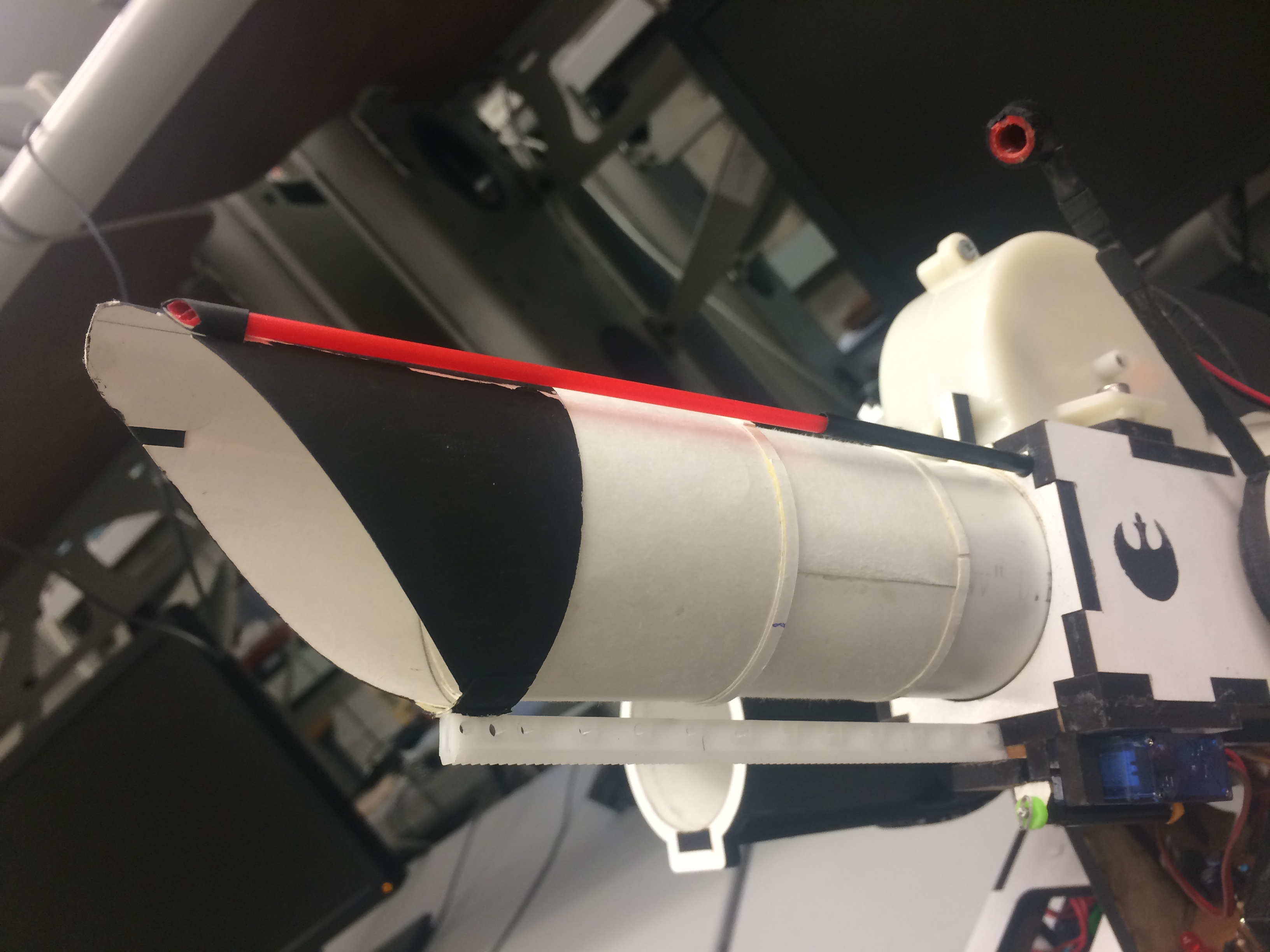
The telescope is made out of paper and we used straws to build a retractil riel to provide more stability and resistance to the mechanism.
Ball Accelerator
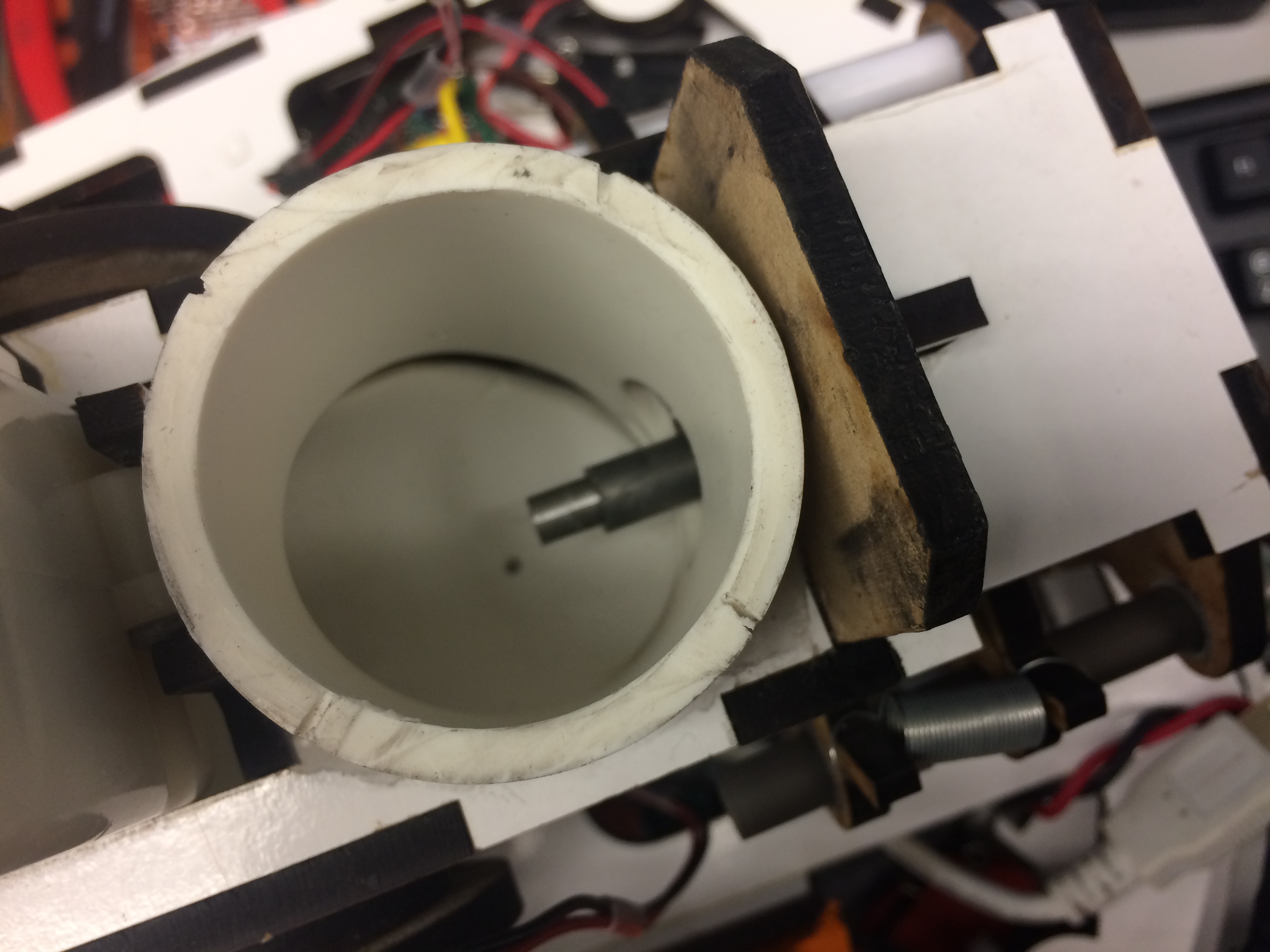
The ball accelerator consists in a foam wheel that spins at a high rpm rate. The friction between this wheel and the ping pong balls is what allows this mechanism to shoot. The image below shows the detail of the entire shooting mechanism.
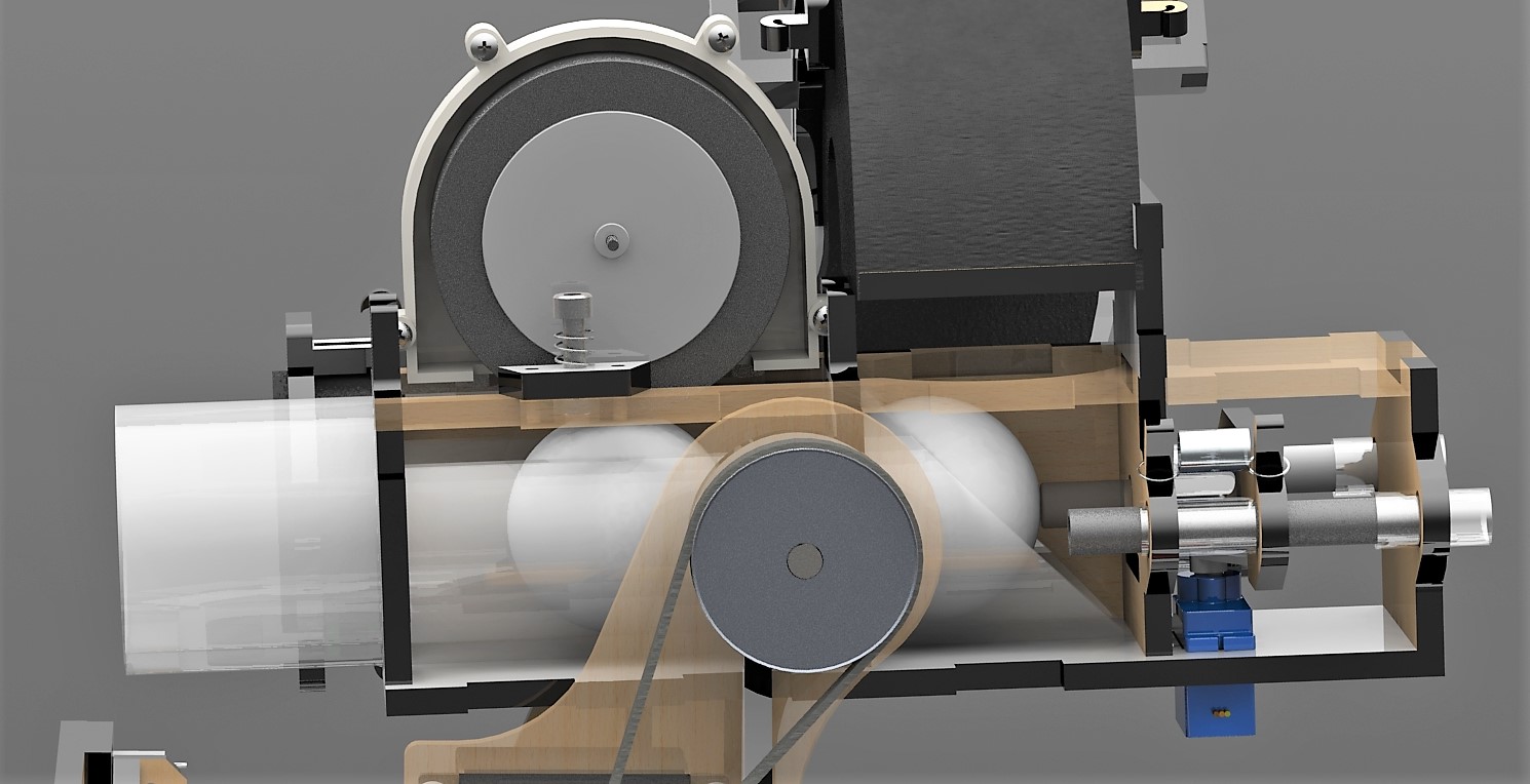
We can see the interior of the acceleration wheel component. This off the shelf solution was very useful for the prototyping process. To mount this component we used springs that allowed to a fine adjustment of the contact between the acceleration wheel and the ping pong ball. In the back we can see the trigger mechanism that pushes the ball to the wheel and also controls the ball supply.
Ball Container
The ball container mechanism is designed to provide a minimum of six consistent shots. During testing we notice that the shooter was more reliable and had lower jamming rate when a little pressure was placed on the ball to be shot. With this observation we came up with the idea of a ball container that had that constant pressure to the balls. We used rubber bands to provide this constant pressure to the balls, also this mechanism allow to save space and carry a very good amount of ammunition.
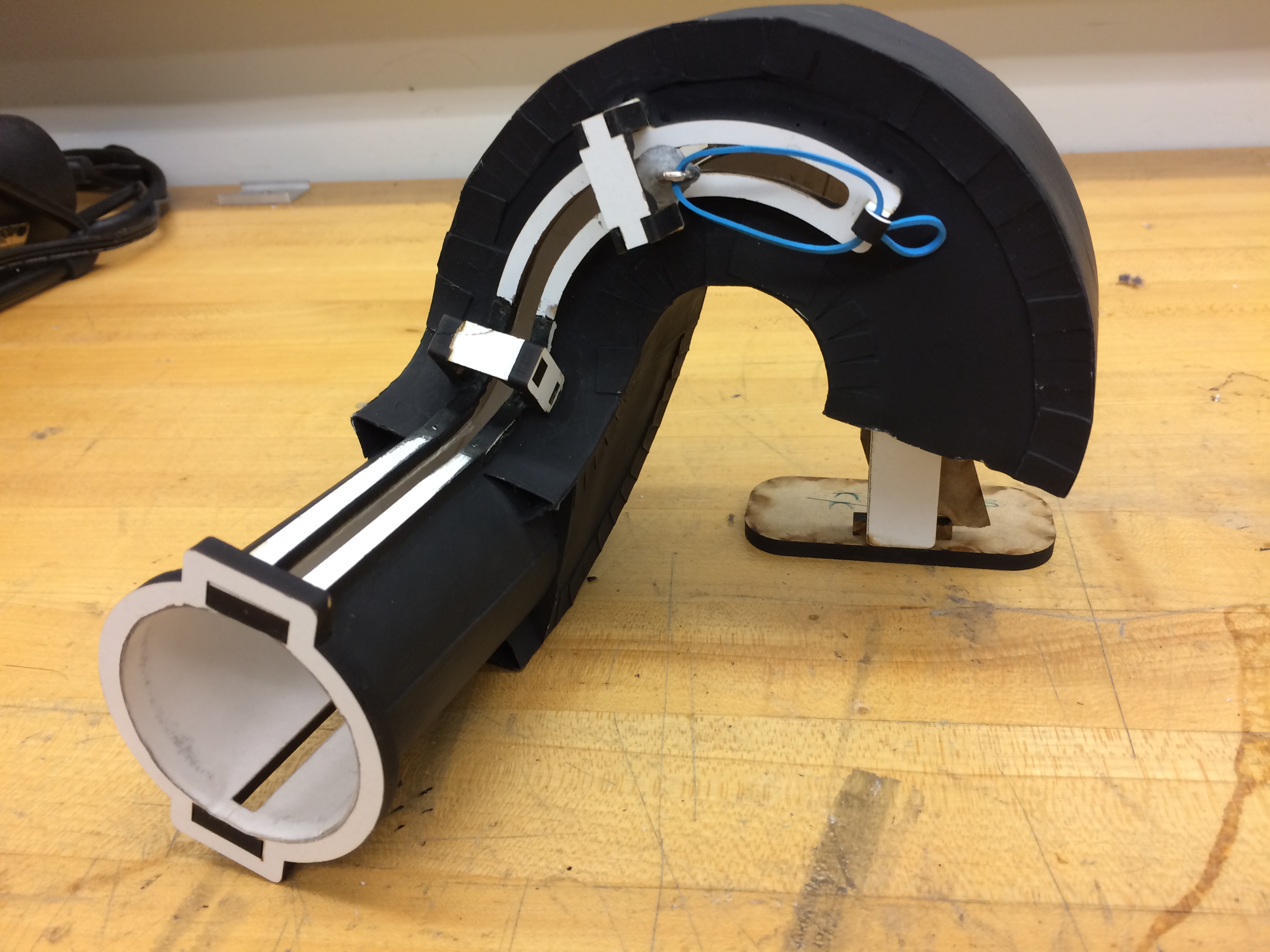
Besides the several advantages that this ball loading method had, there were also several challenges to made it work. One of the most difficult things was to avoid jams due to friction on the rail, to solve this problem we used a polished metal bar with a diameter much smaller than the rail with a glued washers in each side to keep it in its position.
Split Rail Buffer
We are supplying our circuit with 3.3 Volts, and using a split rail buffer to supply 1.65 Volts to give our tank circuit and gain stage an offset so that it could generate a sine wave. In addition, the unity buffer is impedance isolated from the output shown in Figure 19.
Tank Circuit
This is a LC oscillator that resonates at 25 kHz, shown in Figure 20. Since the track-wire is around 24 - 25 kHz, it will induce a large oscillations in the tank, which we could use to detect voltage.
Shown in Figure 21 is a 3 stage cascaded non-inverting gain stage, to amplify the tank circuit signal enough so we can receive it from 3.5inches to 4.5 inches away.
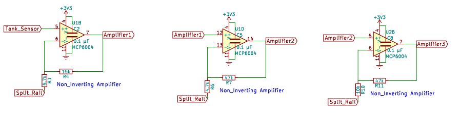
Once we have the signal from the gain stage, we would feed that analog output to our Uno32 microcontroller, so that we could use that value to locate and aim at our AT-M6 targets
Beacon detector
We are designing a 2 kHz beacon detector circuit to help our robot orientate itself at the start of the attack. In addition, it is also used to see indicate when to attack the final target, Kylo Ren’s ship. Figure 22 shows the Beacon Detector top level block diagram.
Split Rail Buffer
Same as the circuit in trackwire, we are using it to provide an offset of 1.65V, and it also provides impedance isolation for all the other circuit that uses this source.
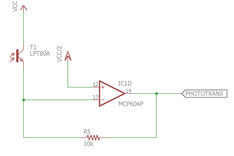
Trans-resistive Phototransistor Circuit
We designed a sourcing configuration of trans-resistive circuit, shown in Figure 23. because there is more collector current flow when incident light increases, and the output could be amplified using the feedback resistor.
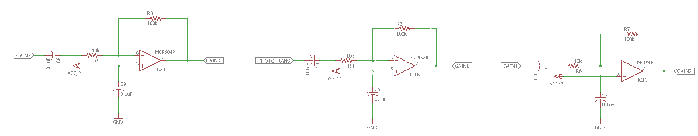
Gain Stage
Shown in Figure 24 is a 3 stage cascaded non-inverting gain stage, to amplify the phototransistor signal so it could be detected from at least 6 feet away. The reason we need this much gain is because at the start of the attack, the beacon detector will be 6 feet apart from our starting position.
First Comparator
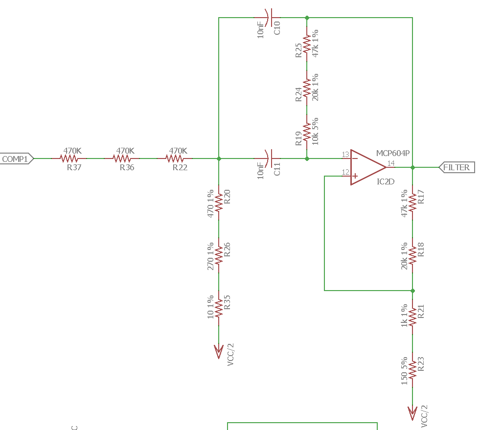
This analog comparator is used to rail all the signal to 3.3V before feeding it to a filter. The reason to rail all the signal is because the filter will cut off all the unwanted signal so that we can see a distinct voltage difference between 2 kHz signal and other signals from 2 feet away or 6 feet away.
Butterworth Bandpass Filter
We implemented a 2nd Order Butterworth Bandpass Filter to cut off 1.5 kHz, 2.5 kHz signal and pass 2 kHz signal, shown in Figure 26. The reason we choose a Butterworth filter is because it is optimized for constancy of amplitude response in the pass-band.
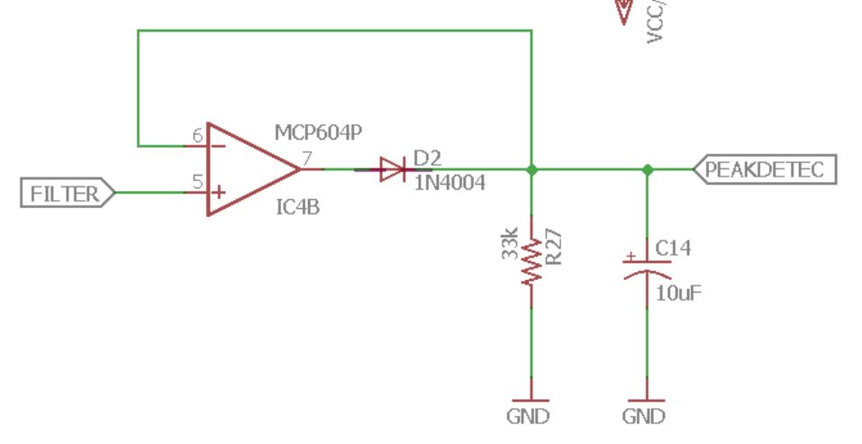
Peak Detector
We are using the peak detector to hold the output of the filter high at different frequencies. The peak detector stores charge on the negative input using a capacitor. The diode prevents discharging, so the op-amp can only raise the voltage on the capacitor, but cannot lower it. In addition, a simple resistor can be used to make the peak detector “leak” charge off of the capacitor. The voltage output of the filter will be different at 1.5 kHz, 2 kHz and 2.5 kHz, which can be used to generate a high or low signal for the micro-controller.
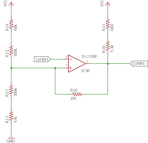
Second Comparator
From the above peak detector, we can find two threshold for 2 kHz signal to create a hysteresis bound so that our beacon detector will only generate a high signal when it detects 2 kHz. In order to do this, we used another analog comparator shown in Figure 28.
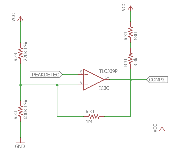
Using the output from comparator 2, we can feet this signal to a digital input of the microcontroller, so that when the beacon is on, our detector will generate a high signal to the microcontroller to help us navigate the field and attack Ren’s ship.
Tape Sensors
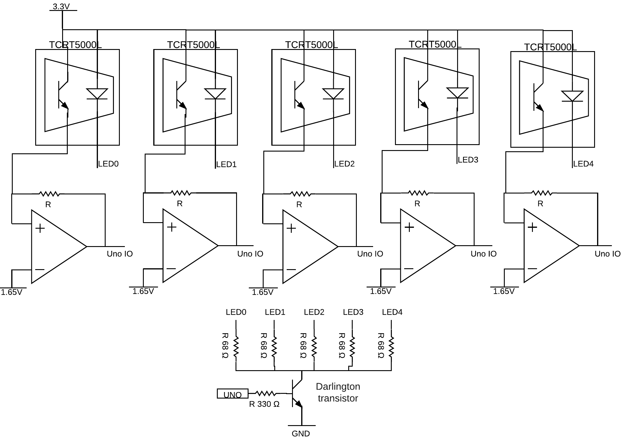
We designed a sourcing configuration of the phototransistor to detect black tape, circuit is shown in Figure 29. Since our microcontroller can not supply 20mA, therefore we are using a darlington transistor to provide 20mA to drive each LED. The voltage across the LED is 1.25V, in order to drive 20mA, we needed (3.3V - 1.25V - 0.4V) / 20m = 82 ohms, and the closest standard resistor is 68 ohms. Our microcontroller can supply about 7mA of current, therefore, the base resistor is (3.3V - 1.4V)/7mA is about 330 ohms, where 3.3V is Vcc, and 1.4V is the base to emitter voltage.
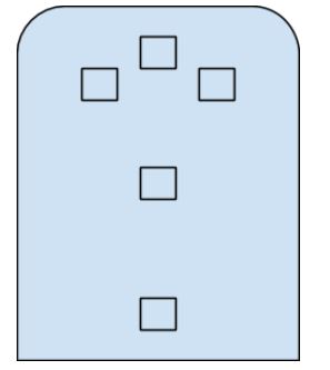
Placement
We choose 5 tape sensors to help our robot to stay in bound and tape follow. Figure 31 shows the placement of our sensor. In the Software Architecture section, we will be going into more detail of how we are using these tape sensor to navigate the course.
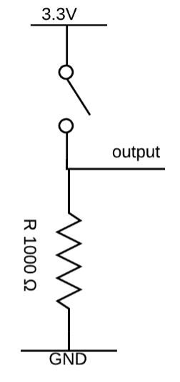
Bumpers Sensors
We implemented the bumper circuit with a pull down resistor, so that when the bumper is pressed, the output is high and when the bumper is unpressed, the output is drive to ground.
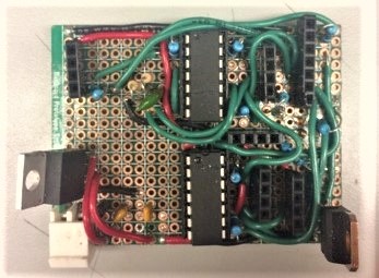
Wire Management
There are a lot of different circuit components, and wires can easily become tangled, making them difficult to work with, sometimes resulting in unplugged wires as one attempts to move a cable. Any kind of problem diagnosis and future updates to such enclosures could be very difficult. Therefore, we made all the circuits ribbon cable compatible to keep wires untangled and organized.
Driving Actuators
H-Bridge
In order to drive the motor, we are using the H-Bridge to sink current so that our power distribution could drive enough current for the motor to spin. In addition, the H-Bridge can provide bi-direction for the motor through logical high and low.
Tip 122
Since our microcontroller can only provide about 7mA, therefore, to drive other servos and shooting motor, we are using TIP-122 transistor to drive enough current for motors and servos to operate.
Software Architecture
We implemented our system using the pattern of state machines. This design was a good fit to the problem because we required fast response to events that may come at unpredictable times. To help us achieve this task we used the provided ES Framework. It provides an easy means of getting timed events. The framework is also flexible enough to expand and create new events and event checkers.
We implemented the state machine in two layers. We used the concept of hierarchical state machines to encapsulate the complexity of doing certain tasks repeatedly.
State machines
Top state machine
The Top state machine is responsible of handling the transitions between the sub-state machines.
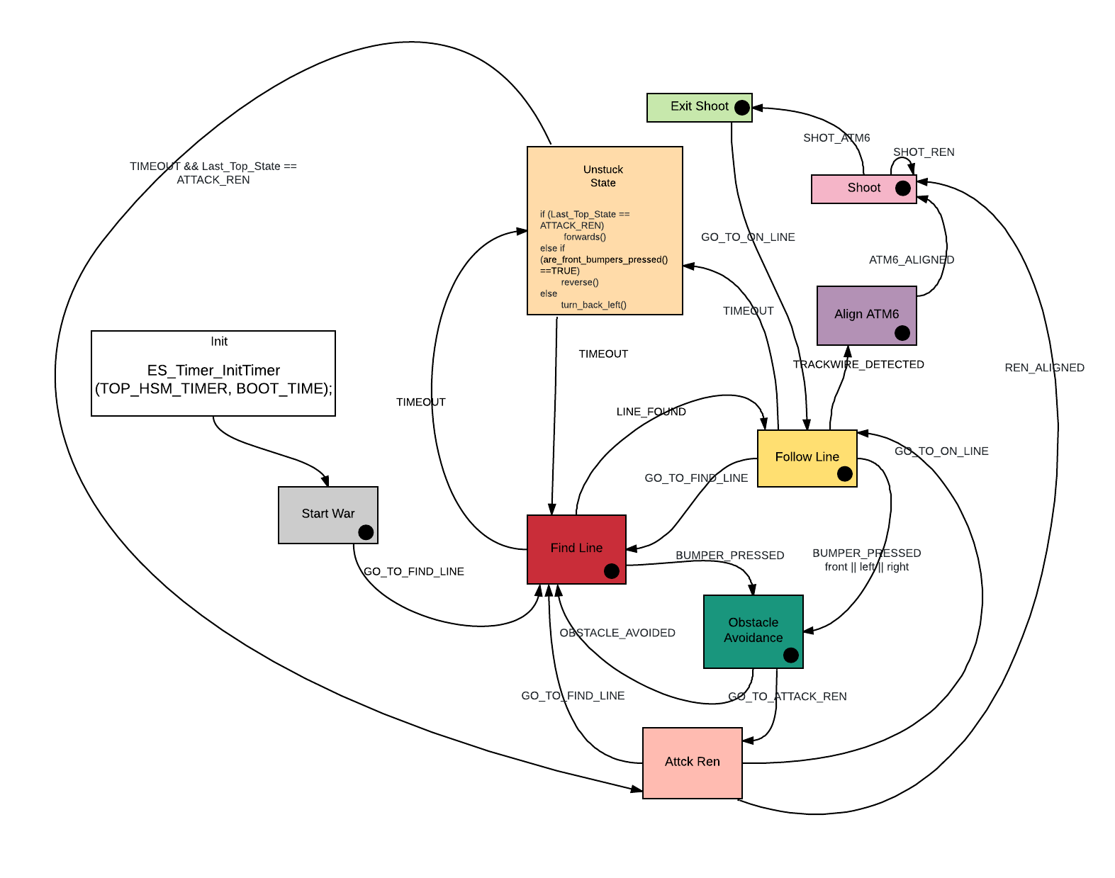
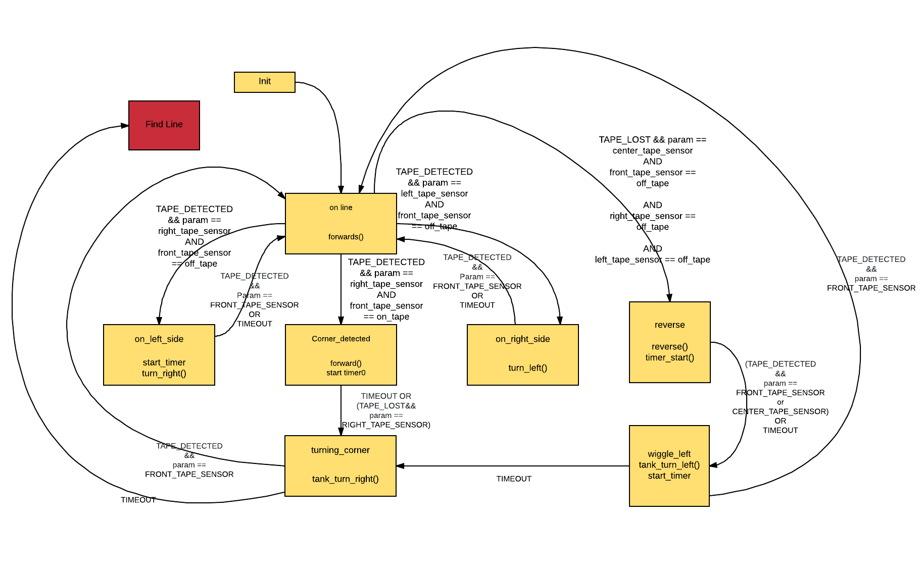
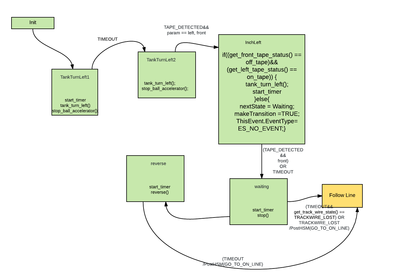
Find Line
This substate is responsible for finding a line and positioning the robot so that it can follow it. This state transitions into Line Follower state as soon as it senses that the robot is aligned with the tape.
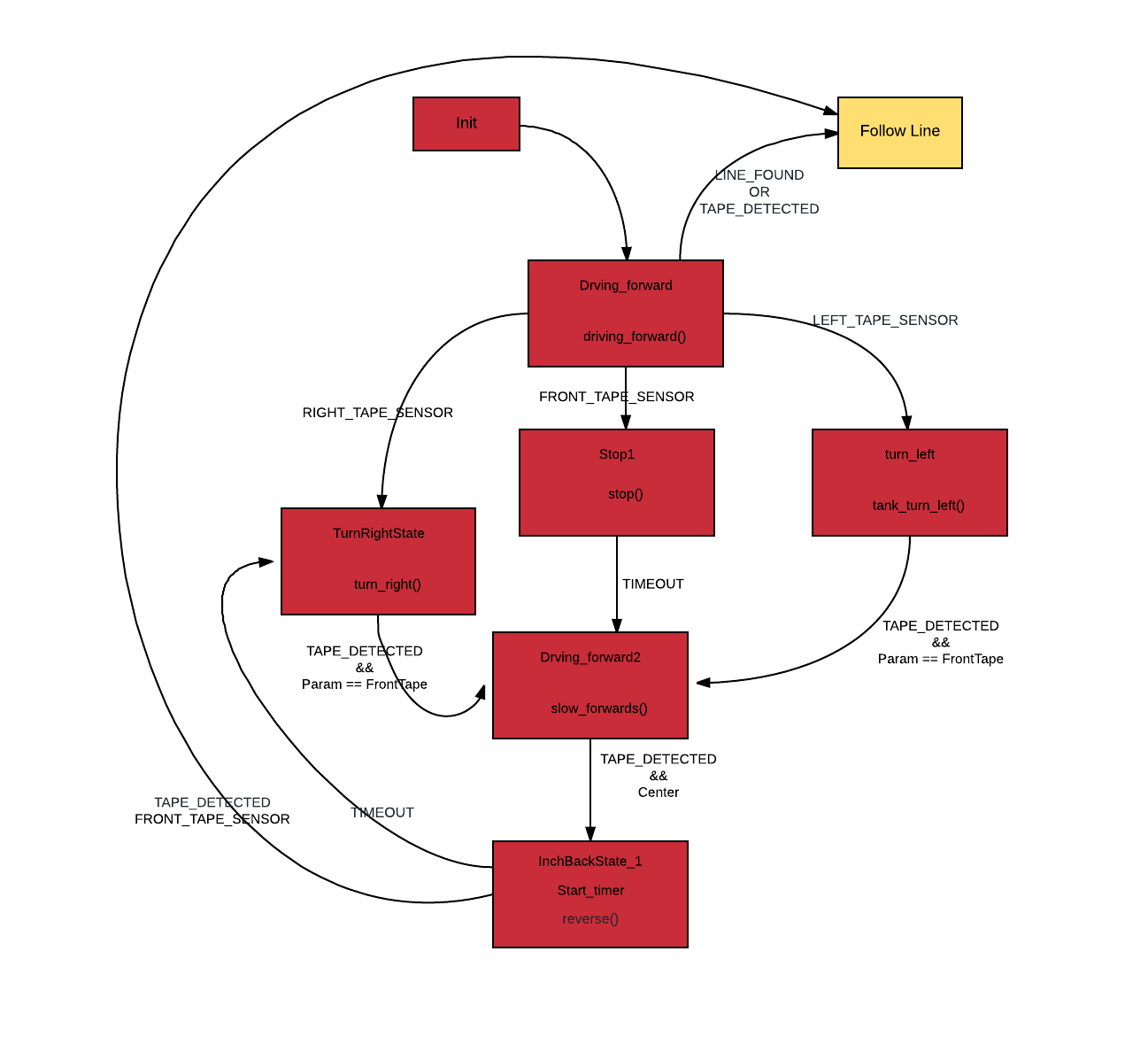
Line Follower
After the robot has been positioned properly, in this state it will move forwards and follow the line. It will exit this state if the bumpers are pressed or if a track wire is detected.
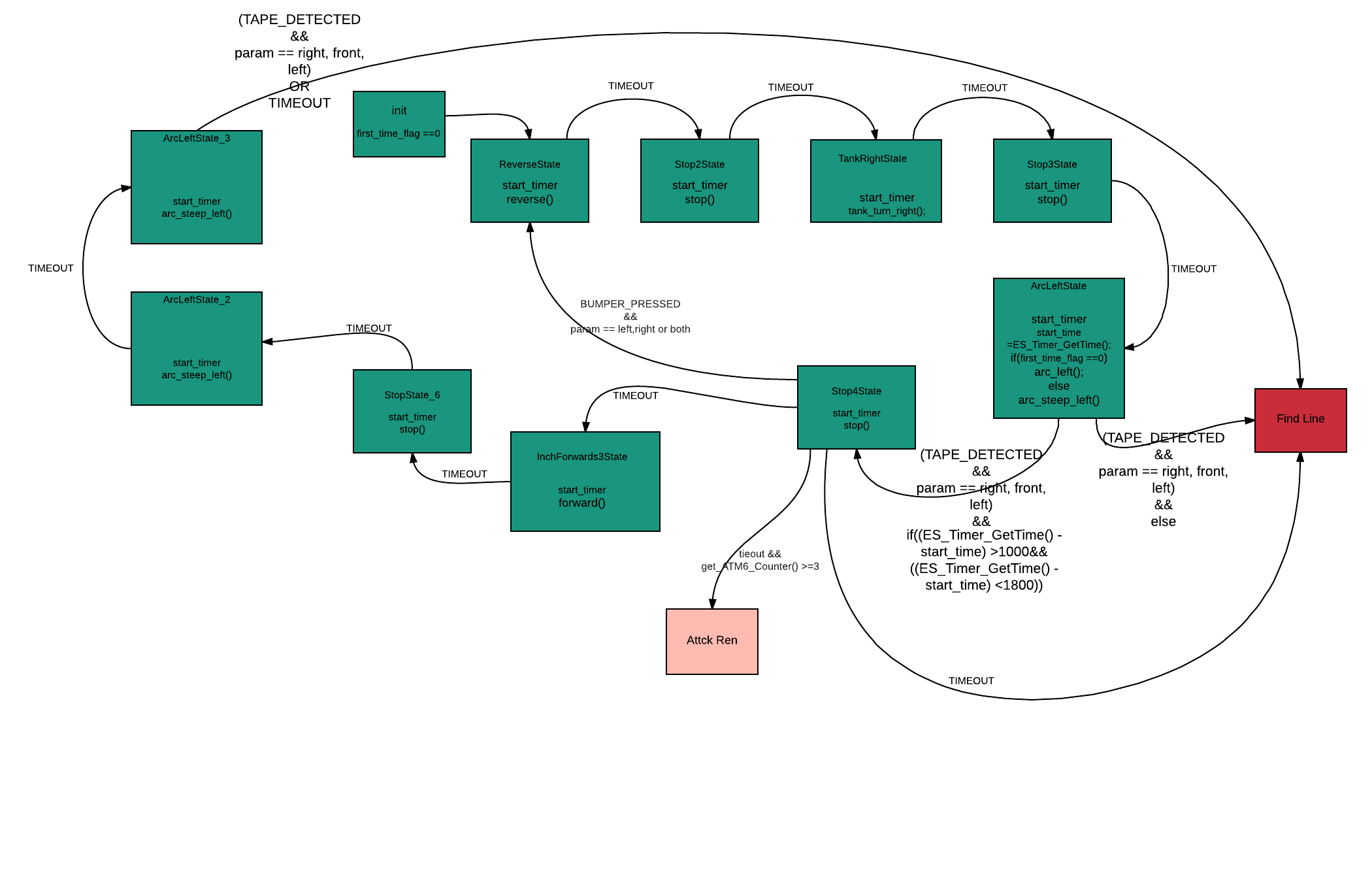
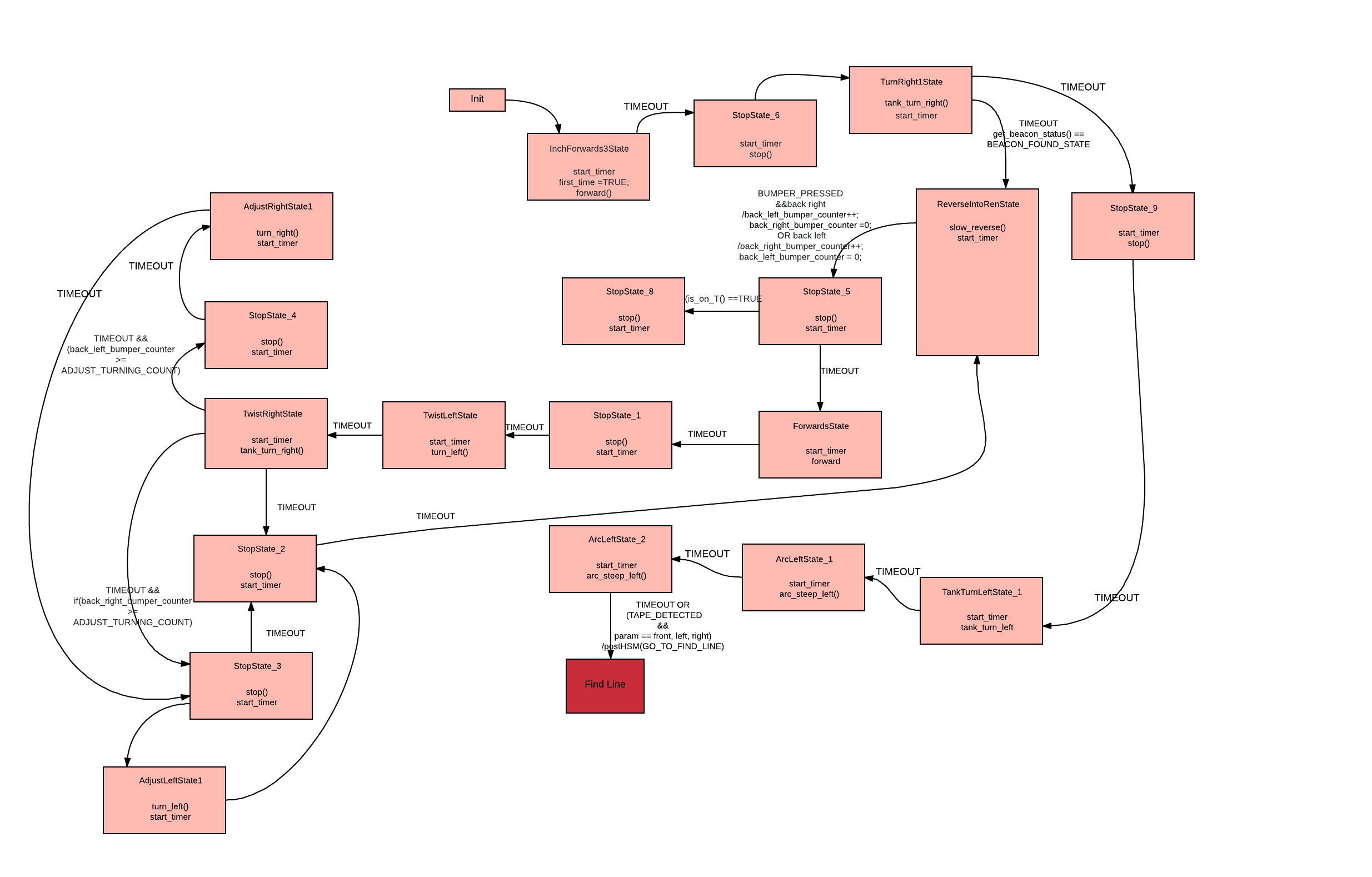
Obstacle Avoidance
In the case that the robot encounters an obstacle which is detected by the bumpers. It will go into this state which is responsible for going around the obstacle and finding the tape again. This state may also exit if it finds the beacon after it has hit at least one ATM6.
Align ATM6
The role of this state machine is to align the shooting mechanism with the ATM6. The robot enters this state from the Line Follower and it detects a trackwire. This state turns around and enters the Shoot state.
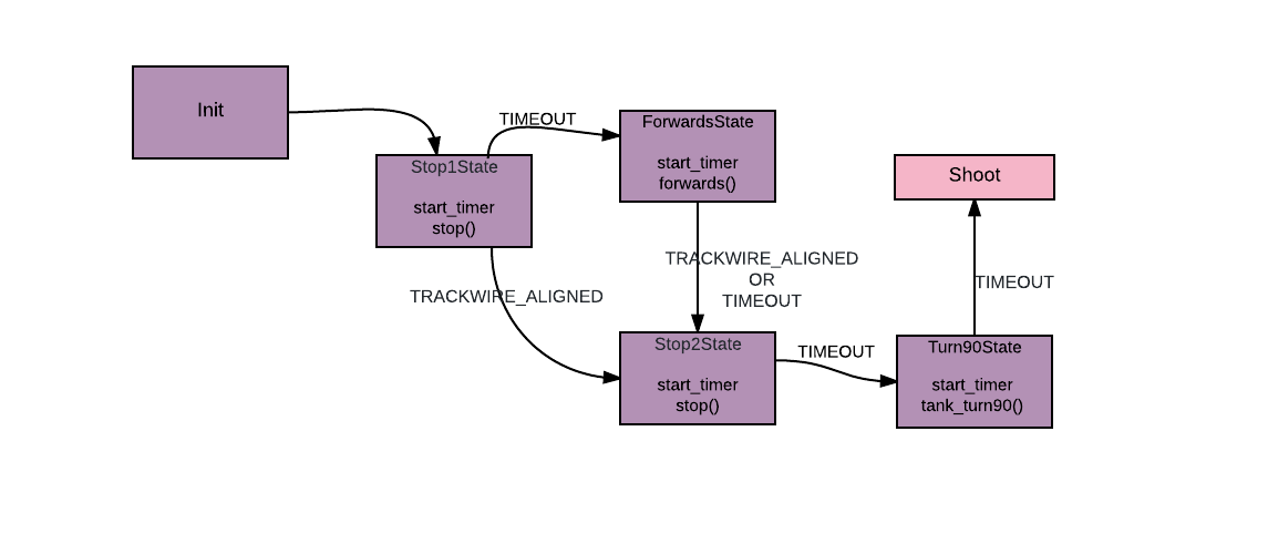
Shoot
The Shoot state is responsible of setting of the series of events required for a successful shot. We are using a complicated system that requires precise timing. We start a motor that has a rubber wheel attached and it needs to reach a certain minimum speed before a ping pong will successfully go through it with the necessary speed. If we are shooting the Ren, we have the extra step of extending the barrel. After this we need to run a servo to release a ball and push it to the accelerator wheel.
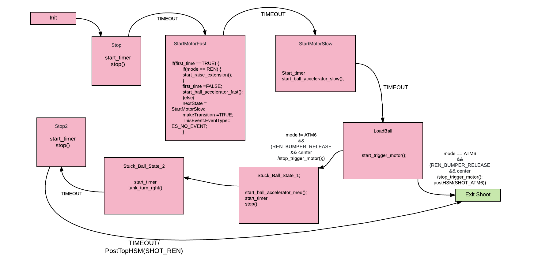
Exit Shoot
The robot goes into this state after each shot to the ATM6 and it takes care of aligning back with the tape and ensuring that the shot was successful. Once a shot is successful the trackwire goes off.
Attack Ren
In this state the robot aligns with Ren until it finds the tape T. Once it finds it it transitions to the Shoot state with the Ren flag on.
Event Checkers
We needed to infrastructure to generate events when physical changes occurred. Some of this changes were detected by event checkers others by services. We used event checkers to run as fast as possible the code to check for changes in our surroundings. We used services for event checkers that could be run at a slower rate or required a delay.
Tape Sensor
We implemented the checker for the tape sensors using a service. We decided to use a service because we needed to guarantee a delay. For our tape sensors we implemented synchronous sampling as a means of getting rid of room noise. We also implemented a moving average as well to account for imperfection in the field. (black dots or white letters on the tape). The service would generate two types of events. TAPE_FOUND and TAPE_LOST. The parameter would specify which tape sensor it refers to.
Bumpers
We also used a service to check the status of the bumpers. We sampled the bumpers at a slower rate to debounce them. We also added a voting system to avoid noise on our system. This service generated two types of events. A BUMPER_PRESSED and BUMPER_RELEASED events. The parameter would specify which bumper the event refers to.
Beacon Detector
The Beacon detector was implemented as an event checker since we took great care with noise measure in hardware. As soon as the digital pin goes high a BEACON_FOUND event is generated. As soon as the digital pin goes low it would send a BEACON_LOST event.
Testing Procedures
We developed and tested the code for the different sensors and actuators independently. We used different main programs to test every component individually. This way diagnosing problems with a particular component meant just swapping to a different main.
Challenges
Accuracy
We struggled to get our shooting mechanism to shoot the Ren reliably. We revised our design and added an extender to the cannon which greatly improved our chances.
Stalling/ slipping (motor problems)
We used a motor that was barely strong enough to move our bot. This introduced great variability in our timed turns. To reduce the impact of this we used turns that relied on looking for tape whenever possible.
Lack of sleep
As the quarter progressed we started to feel the pressure of the deadline and we responded by spending more and more time in lab. This created other problems because we would write code while somewhat sleep deprived.
Conclusion
We successfully built a machine capable of finishing the task. The robot we built managed to complete the task under two minutes. Even though we designed our robot to be robust, there was still great variability in its performance. We partially attribute this variability to change battery levels, slipping/stalling of the wheels on the field and our algorithm for line following. If we were to redo this project we would chose motors with more torque and an algorithm that follows the line more closely.